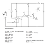
1.5 Volt AM Transistor Radio Schematic and Layout
A 1.5 volt (AAA battery) am receiver circuit diagram
|
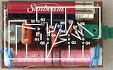
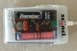
The image on the left is a schematic circuit diagram of the small four transistor AM radio I mentioned a month or two ago (here). I will also attach the component layout and an image of the radio in its plastic box to this page. In each case, click the image for a high resolution version of the image.
A 1.5 volt (AAA battery) am receiver component layout
|
If you want to make yourself one of these radios, I recommend that you start by making a 'breadboard' version so that you can test the coil (for example) and trimmer to insure that they can tune the region of the AM dial that you are interested in receiving. I used the NPN signal transistors that Radio Shack used to sell in my version - these are typically 2N3904's - I believe. But, it will not hurt to try out the transistors that you intend to use in a breadboard version before you solder the components.
A 1.5 volt (AAA battery) am receiver in a transparent plastic box
|