| Su | Mo | Tu | We | Th | Fr | Sa |
|---|---|---|---|---|---|---|
| 1 | 2 | 3 | ||||
| 4 | 5 | 6 | 7 | 8 | 9 | 10 |
| 11 | 12 | 13 | 14 | 15 | 16 | 17 |
| 18 | 19 | 20 | 21 | 22 | 23 | 24 |
| 25 | 26 | 27 | 28 | 29 | 30 |
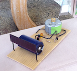 |
This is a solar powered flag waver. It uses a solar cell from an old calculator to charge up an electrolytic capacitor. When the voltage across the capacitor reaches a trigger threshold the charge on the capacitor is released through an electric motor taken from an old video recorder waving a small flag.
I am not the original author of this circuit! Tinker Jim of instructables is! The original article is here: http://www.instructables.com/id/The-Easter-Solar-Engine. It is a really interesting article with lots of carefully researched information. The circuit seems to be nicely reliable - as Tinker Jim describes. It sits on a bookshelf and gradually converts photons into mechanical energy - constantly and gently surrendering to the passage of time.
The power of the flag waving motion is not overly dramatic, it has to be said. But the circuit is a nice example of the concentration of energy in a capacitor followed by its controlled release when a threshold is reached - which is the basis of a wide variety of different circuit types.
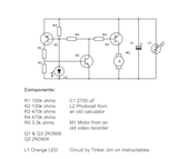 |
The circuit diagram is shown here for completeness - but visit Tinker Jim's excellent Instructable article for all the details.
|
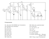
The circuit diagram on the left is an audio to light converter (click the image for a larger view). It lights up a pair of red LEDs based on the sound that it picks up. I made it several years ago - and I think it was based on circuit which drove a meter (or metre if that is your spelling preference) that I saw on Watson's blog - back when that blog was on blogspot. Since then Watson has moved on to his www.rustybolt.info site, and the circuit is no longer present. What I did was combine the drive with a Joule Thief circuit and this seems to nicely light a pair of red LEDs - from a single AA battery.
I always like to have circuits that run on 1.5 volt batteries - such batteries are inexpensive and you mainly buy battery and not padding and packaging - which is not alway the case with higher voltage batteries. So a sound to light converter using a single AA battery is appealing. The circuit uses only a few milliamps so the battery will last for a good long time. Nevertheless, I have an on off switch so that I do not always have the device switched on.
As is always the case, anyone building the circuit would be well advised to start with a breadboard version to check that everything is going to work with your particular component choices. When I made the circuit I clearly could not find a suitable bias resistor for Q2, so I have two resistors in series to get to about 680k ohms. This is one example of the use of a breadboard to check everything prior to assembly makes good sense.
The most important variables in this circuit will be the microphone and the Joule Thief drive for the LEDs. In the case of the microphone, I used a piezo insert type microphone that came to me via an old electronics set. So, I do not precisely know the part number of this component. However, if you start up with a breadboard prototype you can test what will work for you.
The Joule Thief section that I used employs an interstage audio transformer. This is rather unusual for a Joule Thief, but I suspect that the circuit will work fine with a traditional Joule Thief toroidal transformer. (But I should note that I have not tested this). I empirically found that the interstage transformer uses very little power, and I figured that this might be helpful in this particular circuit. The base transistor for the Joule Thief is 120k ohms which is much higher than what would be used in a traditional Joule Thief. But, my empirical observation was that with this transformer, a high value base resistor led to low current consumption. If you are trying out this circuit on a breadboard, you can obviously experiment in this region. Perhaps start by measuring the voltage switched by Q4 and then figure out how you can use that voltage to do something interesting - like drive some LEDs or a motor (etc.).
A final comment is the role of R9, which is a variable resistor that is used to set the sensitivity. In use, you adjust this control such that the LEDs are just switched off in a quiet room. This adjustment point is easy to set and once you have suitably adjusted the device, the LEDs will be nicely sensitive to the sound picked up by the microphone.
As an experimental application, I recorded three videos of the LEDs lighting up in time with sound. The three topical cultural examples chosen were: Hillary Clinton, Donald Trump, and Ozzy Osbourne. I will post the embedded movies below, along with a quick video which shows the device in its transparent box. Naturally, the device works just as well without projecting its lights through a static image of a cultural icon - but this particular application results in an interesting visual effect...and I am sure that other applications can be found.
Ozzy Osbourne
Donald Trump
Hillary Clinton
And the device with no picture...
|
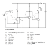
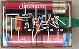
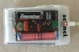
The image on the left is a schematic circuit diagram of the small four transistor AM radio I mentioned a month or two ago (here). I will also attach the component layout and an image of the radio in its plastic box to this page. In each case, click the image for a high resolution version of the image.
|
If you want to make yourself one of these radios, I recommend that you start by making a 'breadboard' version so that you can test the coil (for example) and trimmer to insure that they can tune the region of the AM dial that you are interested in receiving. I used the NPN signal transistors that Radio Shack used to sell in my version - these are typically 2N3904's - I believe. But, it will not hurt to try out the transistors that you intend to use in a breadboard version before you solder the components.
|