Sat Jun 20 20:05:28 PDT 2015
Tone Controls on a Hacker Sovereign II
In 2012, I acquired a Hacker Sovereign II radio. The Hacker Sovereign II is a British 1960s transistor radio, suitable for listening to test matches on long wave, classical music on FM, and some subversive rock and roll on the medium wave.
This particular radio was rather beaten up...the batteries had leaked at some point...and someone had 'adjusted' it to run off one battery and cut a little hole in the box for some unknown reason - possibly relating to supplying power. But, in the interests of nostalgia, and having seen these radios in action in the 60's and 70's, I've been tinkering with it recently.
One interesting discovery was that the capacitor which is connected across the battery had become something of a resistor over the years, hence the battery was constantly supplying a few milliamps (because the capacitor was before the main on/off switch). So, that is one of the reasons that the batteries leaked, I suppose. To fix that issue, I simply disconnected that capacitor (I think its main purpose was reducing hum in the external power supply - which I currently do not have).
But, what fascinated me about this radio when I was a lot younger was that it possessed bass and treble tone controls - just like a stereo. So, having learnt a little about electronics over the years, I was curious about the circuitry.
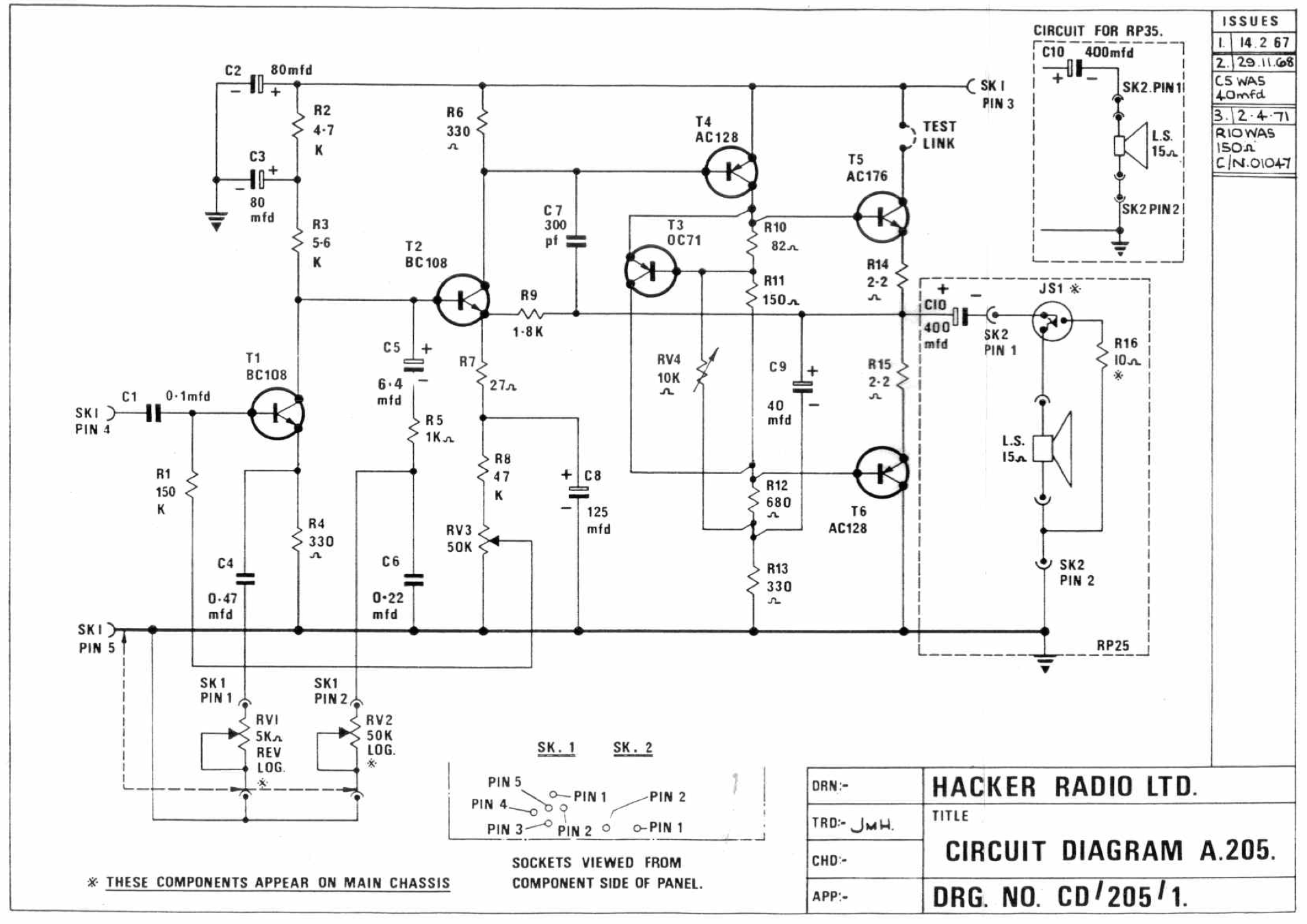 |
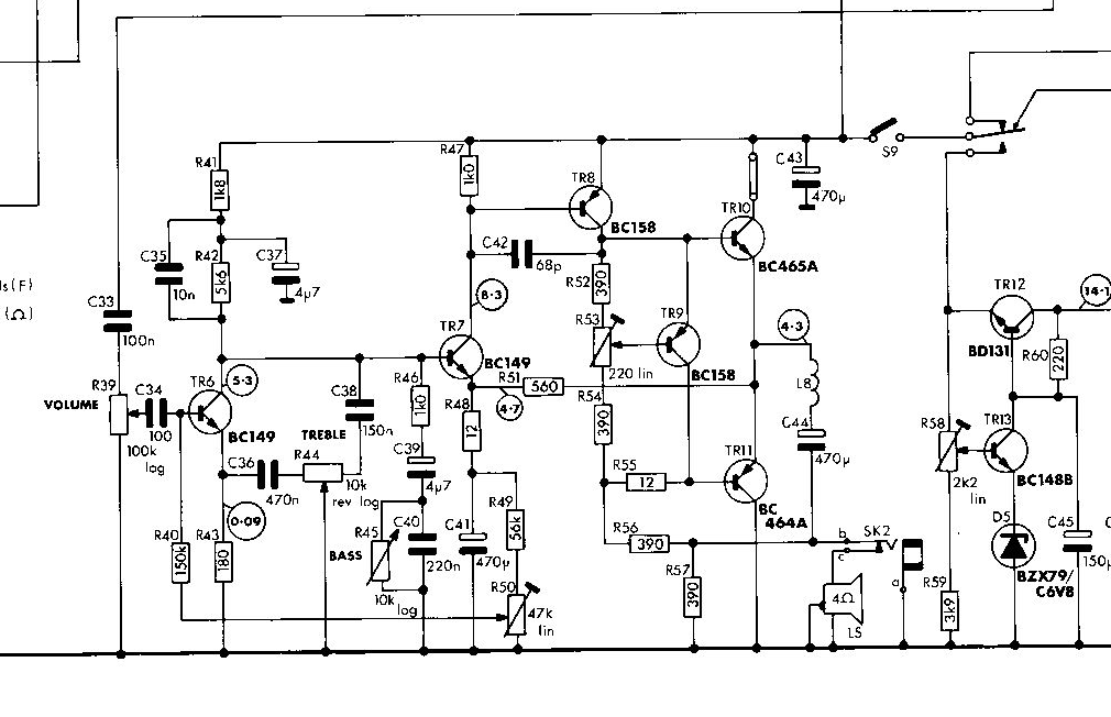
The figure on the left shows the section of the Hacker's circuit which controls the tone of the radio. The tone controls are not in the famous Baxandall configuration in this particular circuit. I speculate that Hacker avoided this to reduce the amount of wiring required (the bass and treble controls only require two wires each as opposed to the three wires each required by the Baxandall circuit) - the number of wires running around inside a radio is important - each wire increases the complexity of assembly and increases the chances for interference. Additionally, the Baxandall circuit uses more components and components cost money. Anyway, Hacker used the simpler configuration that the diagram shows.
The treble control is in the emitter of the first transistor. This works in the following way. There is a relatively low value capacitor, C4, in series with the treble control variable resistor, connecting the emmitter of the transistor to the ground. When the resistor is at zero ohms, C4 increases the current flow in the first transistor at higher audio frequencies. This boosts the treble response. As the resistor value is increase, this boost is removed from the circuit until it has no effect at all, and there is no treble boost. As the value of C4 is only 0.47 microfarads, it only boosts high frequencies as its capacitance is too small to boost the emitter current of low audio frequencies. So with two components, a capacitor and a variable resistor, Hacker added treble boost to their pre-amplifier circuit.
The bass control similarly makes use of a capacitor, C6, but on this occasion the variable resistor is connected in parallel with the capacitor. Here, when the resistance is low, C6 is effectively removed from the circuit, and C5 and R5 take a fraction of all audio frequencies to ground rather than to the second transistor. However, as the bass is turned up, and C6 is progressively brought into the circuit, only high audio frequencies are shunted to the ground, and the bass is effectively boosted (or cut less).
Hence the circuit achieves the required control of bass and treble frequencies with minimal wiring and components. On my particularly radio the controls are still nicely effectively (capacitors and variables resistors can degenerate with age), and I can overly boost the bass and treble if the fancy strikes!
There is something generally satisfying about the economy employed by Hacker. Looking around on the web, I see that Roberts (another brand of British radio) used a circuit which is partially Baxandall and partially Hacker Sovereign II-like. (That circuit can be seen here).
What is the next step in my transistor radio nostalgia (the simplicity of bygone technologies, etc.)...well that might involve working out how to get a reliable non-humming power adapter for the Hacker (and reviving that capacitor that seems to have gone wrong over the years)!