| Su | Mo | Tu | We | Th | Fr | Sa |
|---|---|---|---|---|---|---|
| 1 | 2 | 3 | 4 | |||
| 5 | 6 | 7 | 8 | 9 | 10 | 11 |
| 12 | 13 | 14 | 15 | 16 | 17 | 18 |
| 19 | 20 | 21 | 22 | 23 | 24 | 25 |
| 26 | 27 | 28 | 29 | 30 | 31 |
Here is a simple DIY planner for 2026: 2026-DIY-Planner.pdf.
If you have access to a printer that can print on both sides of a piece of paper, you can print yourself a letter sized 2026 planner using this file. You can then hole punch the pages and put the planner in a binder.
To create this, I used an awk program to write PostScript for the main planner and ps2pdf to convert the PostScript into a PDF. The initial calendar pages came from a combination of another awk program and the cal program.
And here is a shorter pdf which provides monthly spreads for 2026 planning, again for printing out double sided and hole punching to put in a binder: 2026-Monthly-Planner.pdf.
This video shows a transistor tester I put together based on the circuit available here, and also here. The version I made retained the switch to the base connection for the transistor under test from the first link and also included the diodes from the second link. I also changed some of the resistor values based on what I had available.
What appeals to me about this circuit is its simplicity and its ability to discriminate between NPN and PNP transistors. The circuit uses a multivibrator to create an alternating voltage source. This source is fed to two LEDs connected in opposite directions - so that each is lit only when the voltage is in the appropriate direction for that LED. As the capacitor values in the multivibrator are quite low, the AC generated is of high enough frequency that you cannot see the alternating nature of the LED lighting - but it is present nonetheless. Only one LED is lit at a time, the flash alternately at a high rate.
The transistor under test is connected across the pair of LEDs, and it is biased by the 1k resistor so that it will be turned on for only one of one phase of the AC cycle. NPN transistor transistors are only turned on when when the right hand side of the LED pair is positive and PNP transistors only when the right hand side of the LED pair is negative. When the transistor is turned on, it stops the LED with the same orientation as the transistor under test from lighting. Hence, a good transistor will result in one LED turning off, and depending on which transistor is turned off, the nature of that transistor (NPN or PNP) can be discerned.
The 4 diodes in the collector connection for the transistor under test mean that there will always be two diodes, dropping 1.2 volts, before the transistor under test is reached. This means that the transistor itself must drop less than 0.6 volts to turn off its LED indicator diode. If the 4 diodes were not present, a transistor which was not functioning as a transistor but just as a diode would appear to be a functioning transistor in the tester.
Here is how the astable multivibrator works:
And here is the circuit diagram.
 |
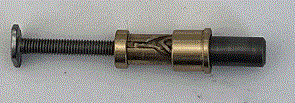
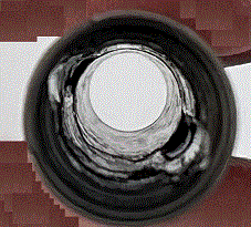
A while ago I adjusted a Zebra F701 to allow it to take a wider variety of refills. I followed the instructions in the following video:
Or - using a regular link...
https://youtu.be/5a7ed3Bk6CcThis is a fantastic video. It shows you how to disassemble the pen and modify it in various ways.
For my purposes, I simply followed the instructions to make the 'push and twist to lock' variant of this pen. This involves punching two bulges into the brass tube at the top of the pen and filling two flat spots on the pusher.
As you can see in the photographs below, I was not terrible careful in the way that i went about making the adjustments. They could be done much more neatly. The brass is quite soft, so it does not take much effort the file and saw the necessary changes.
After the changes are made, the pen can accommodate longer refills, which is very convenient. And, if anything, the changes improve the balance of the pen.
 |
 |
 |
 |
 |
Or - using a regular link...
https://youtu.be/EXJqzkWiqhUI made a 1.5 volt battery powered LED flasher last weekend - following the circuit diagram published by Burkhard Kainka (see https://www.b-kainka.de/bastel59.htm). This uses a tiny amount of current and one AAA cell last for several hundred days. It also meets the important criterion of fitting nicely into a TicTac packet - as the photograph shows.
I wanted to describe how the circuit worked, so I tried using LT-Spice for the first time. Having watched a couple of YouTube videos, I felt suitably educated, downloaded the program, and gave it a go. It works very nicely. The image below shows the circuit and the LT-Spice simulation of the voltage at key points.
 |
The operation of the circuit is as follows...
To start with all the transistors are off, and the 100n capacitor is charging through R1, R4, and R6. When the 100n capacitor gets to about 0.6 volts, Q2 turns on, and turns on Q3, which is a pnp transistor. As soon as Q3 turns on, Q1 is turned on via R7, and this turns off Q2 and then Q3. So, Q3 is only turned on for a brief moment. However, Q3 being on charges the right hand side of the 100n capacitor, and Q3 turning off connects this capacitor to the negative rail. As all voltage are relative, and the 100n capacitor has its positive side connected to the negative rail, this has the effect of making the base of Q2 have a negative voltage, as can be seen in the LT-Spice simulation. Then the 100n capacitor begins to charge again, and the cycle is repeated when the base of Q2 gets to about 0.6 volts.
So that is how the circuit oscillates. The circuit is able to flash a LED, using a 1.5 volt battery, by using the oscillation in the following manner. 1.5 volts is not enough to drive a red LED, so the circuit is configured to charge up the 100uF capacitor through resistors R2 and R5, such that the right hand side of the 100uF capacitor is at +1.5 volts and the left hand side is at 0 volts. However, when Q3 opens open briefly during its oscillation cycle, the left hand side of the 100uF capacitor is connected to the positive rail, this puts the battery effectively in series with the charged up capacitor, and generates enough voltage to drive the LED giving a brief flash of the LED.
So that is how this LED flasher works. It will be very interesting to see how long it runs :-)
There are some examples on Burkhard Kainka's website of other versions of this circuit. One uses a second charge holding capacitor to increase the voltage for the LED further, so that a 1.5 volt battery can light a blue LED. I might try that next...
A while back I was inspired by circuits like this: https://bestengineeringprojects.com/all-in-one-tester-circuit/ to make a transistor based continuity tester that uses red and green LEDs to indicate test results. It turned out that I did not succeed in getting the published circuit to work satisfactorily. But with some modifications, I made a closely related circuit that works. The circuit is shown below.
 |
The major changes were to avoid using a two color LED, and instead using two LEDs. I also found it necessary to change the circuit around a bit. I am not sure why this should be the case. I wanted the circuit to work at 4.5 volts and perhaps this was the difference.
Here is how the circuit works. When the circuit is powered on, the second NPN transistor is biased into conduction by the 180k resistor, and the red LED is illuminated.
When the leads are connected together, the first NPN transistor turns on, this turns of the second transistor. The green LED is then illuminated, and the red LED is turned off because the second transistor is turned off.
The circuit can be used as a continuity tester, it can test electrolytic capacitors (see below), and it supplies enough current to light LEDs, which can be useful for checking their operation.
Checking an electrolytic capacitor proceeds as follows. The positive and negative leads of the tester are applied to the positive and negative leads of the capacitor. The current flow though charging the capacitor will initially turn on the first transistor and therefore the red LED. However, when the capacitor is charged, current will cease flowing, the first transistor will turn off along with the green LED, and the second transistor and red LED will turn on. This color change over confirms that the capacitor is working correctly.
The circuit applies around 1 milliamp at about 3.5 volts (approximately) to whatever it is testing. So, it can make LEDs glow dimly (and safely), if you want to test such devices.
So far it has proven quite useful. And it fits into a Walmart sized TicTac mint box, which is a definite plus!
 |
Or - using a regular link...
https://youtu.be/WJ5W5Svsa8YThe image below and the movie above show an ionizer circuit I built using a voltage multiplier - along with its neon indicator to show that it is working. The movie shows that there is a faint bluish glow produce at the tip of the needle - so the ion generation is also generating ozone. Ozone is not particularly good for you - so if you make this circuit - please be aware of this fact and only build this at your own risk. The circuit also creates high voltages, so again build this only at your own risk, and only if you are comfortable working with circuits that might give you a substantial electrical shock.
 |
The circuit used to generate the AC with which the voltage multiplier is fed came from the excellent TechLib site: https://techlib.com/electronics/flasher.html. The interesting parts of this circuit are the transformer - I used the transformer from a phone charger. Having extracted this from the phone charger, I found the coil with the least resistance as used this as the primary, and the coil with the highest resistance to use at the secondary. In testing, this gave about 300 volts AC (very approximately), but the measurement depended on the meter I used, so I would not trust it overly much. I found that when connected to the voltage multiplier the circuit could generate about 1500 volts (I believe) and this was sufficient to produce ozone. The voltage measurements are very approximate. I found that it was important to choose the correct polarity of the secondary windings - I suspect that this is because the wave form produced by the oscillator is highly unsymmetrical.
I took the voltage multiplier circuit from the also excellent Big Clive site: https://www.bigclive.com/ioniser.htm. I particularly like the neon indicator, which shows when the circuit is working. I did not use a high voltage resistor for the output resistor - and I used only a 4.7M ohm value - but it seems to work alright. I also used a much lower value capacitor for the neon indicator - but apparently this also works just fine. I built the oscillator because, unlike Big Clive, the local mains for me is 110 volts (which would require a lot of capacitors and diodes) and I did not want to mess with a mains powered ionizer - which would probably be extra dangerous.
If you want a clear explanation of the voltage multiplier circuit - there is really good one here: https://youtu.be/ep3D_LC2UzU. The basic idea is that the first capacitor in series with the transformer is used to store charge which is added to the input wave form to shift the input voltage peaks to twice their initial value. The second capacitor is then used to create the steady ground for the new wave form. The diodes are used switch the charge when the wave form changes polarity, and each subsequent stage repeats this process shifting the voltage from the transformer up in value by the peak height in the waveform. So the nine stages of the voltage multiplier circuit multiply the voltage by a factor of nine. (EEVblog explanation linked above is excellent - so refer to that explanation for details).
As usual, I built the circuit using a breadboard first in order to test everything prior to soldering the components. The circuit runs from a lithium ion power bank and it only uses about 30 milliamps - so it can be left running for long periods of time.
Or - using a regular link...
https://youtu.be/NyY173qtp3QThe image below and the movie above show a neon light flasher I made based on a Joule Thief oscillator.
 |
The circuit is very simple. The coil is custom wound on a ferite core from a power supply. The relatively high voltage alternating current from the coil is rectified by a set of diodes and used to charge a 0.22 microfarad capacitor which is discharged through a neon to create a flash. The circuit runs for about 4 days from on an AA battery.
Although the circuit is simple. I had to make some discoveries to make it work. I made it first using a breadboard so that I could find out what worked before soldering the components together. Here are some of the things things I found making this circuit.
Firstly, the waveform of the oscillator is not very symmetrical - so it makes a large difference which way you decide to orient the diodes. I tried both directions and picked the one that was able to produce enough charge to cause the neons to flash. I learned about this from Alan Yates' very interesting site: http://www.vk2zay.net/article/30.
Secondly, I found that the transistor in the circuit slowly stopped working - which was a surprise. What happened was that the amount of flashing gradually declined. After a few AA batteries had been used (so many days worth of use), the flash rate had become noticeably significantly worse than when the circuit was first made. At this stage, inspired by the types of circuit that one sees for CFL lights, I put in a diode across the transistor so that negative spikes are taken to ground without troubling the transistor. This solved that problem as the present transistor does not appear to be declining as use continues.
Thirdly, I found that the coil needed to be kept off the perforated circuit board with a pad of insulating tape. I am not sure why this should be - perhaps the perforate circuit board I used is not that great an insulator - but performance is much better when the coil is separated from the board by some insulation tape, so that is what is now done.
I wound the coil as an experiment, to see if this would work. I took a ferrite toroid from a power supply (it was colored green - perhaps the color signifies its ferrite properties) and wound about 300 turns of thin enameled wire onto, starting on one side and progressing around until the end was about one quarter of an inch from the beginning. I then wound a 4 turn Joule Thief onto the middle of the fine turnings. I assume that the smaller the number of turns in the Joule Thief coil the higher the output voltage, because the voltage is governed by the ratio of the primary to the secondary. However, the Joule Thief needs a reasonable inductance to oscillate. I found that 4 turns worked so I did not experiment with this variable.
As you can see from the schematic, I varied the size of the resistors that feeds the 0.22 microfarad capacitors by putting a 1M and 220k ohm resistor in parallel. You could just use a 180k resistor here. I was experimenting to get a reasonable flash rate - hence the parallel resistors.
As noted above, I would recommend that you build this on bread board first to get the component values and coil correct before soldering the components together.
Measuring the output of this coil when energized by the Joule Thief circuit is a little challenging for me - as I just have a cheap multimeters and I suspect that the AC waveform is very unsymmetrical. It is very different using an analog multimeter to the value that a digital multimeter gives, for example. However, when used as a source for a neon oscillator - there is enough voltage to achieve that objective. Basically what happens is the voltage across the 0.22 microfarad capacitors gradually increases until the neon lights, which removes the charge and the process begins again.
The circuit can give you a reasonable shock if you are not careful - so build the circuit at your own risk only - and take care to discharge the capacitors before you touch them.
Here is a simple DIY planner for 2025: 2025-DIY-Planner.pdf
If you have access to a printer that can print on both sides of a piece of paper, you can print yourself a letter sized 2025 planner using this file. You can then hole punch the pages and put the planner in a binder.
To create this, I used an awk program to write PostScript for the main planner and ps2pdf to convert the PostScript into a PDF. The initial calendar pages came from a combination of another awk program and the cal program.
And here is a shorter pdf which provides monthly spreads for 2025 planning, again for printing out double sided and hole punching to put in a binder: 2025-Monthly-Planner.pdf
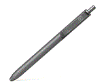
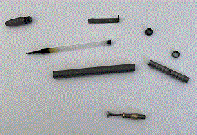
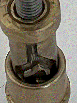
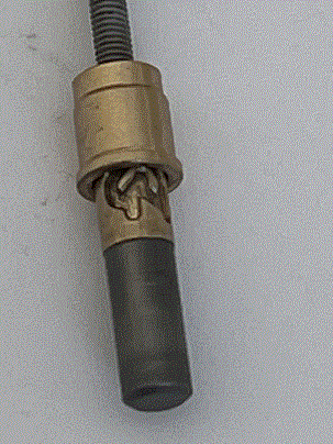
I bought a Big Idea Design Slim Click Pen. It is rather good! It is made of titanium - which is light and strong and it can accept a very wide range of ink cartridges. If you like pens - you will appreciate this pen.
Here are some pictures of the pen and its internals, that show (basically) how it works.
 |
 |
 |
 |
 |
 |
Here is a simple DIY planner for 2024: 2024-DIY-Planner.pdf
If you have access to a printer that can print on both sides of a piece of paper, you can print yourself a letter sized 2024 planner using this file. You can then hole punch the pages and put the planner in a binder.
To create this, I used an awk program to write PostScript for the main planner and ps2pdf to convert the PostScript into a PDF. The initial calendar pages came from a combination of another awk program and the cal program.
And here is a shorter pdf which provides monthly spreads for 2024 planning, again for printing out double sided and hole punching to put in a binder: 2024-Monthly-Planner.pdf